Prologue
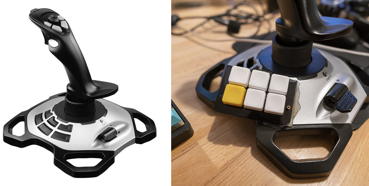
Logitech Extreme 3D Pro is a legendary joystick/flightstick, however you want to say it. It was released in 2003 and it is still in production and sold for around 50€. You can get these for cheap. The joystick itself is really basic, but gives you a good variety of buttons and features for a small price. Even if the name gives you a small hint, that there might be a casual version of the joystick, but on the contrary, there isn’t. Only for Pros'!
I bought mine from a friend and it was just barely used. I needed the joystick for the new Microsoft Flight Simulator (2020) and Star Wars: Squadrons games. The Squadrons was relatively nice singleplayer fly and pointy shooty game, but the MSF2020 was amazing. I really recommend it.
But this is not a game review - no! This is about LogiMech, an amazing project to improve Extreme 3D Pro’s biggest downfall - sidebuttons.
Sidebuttons
By default, the joystick uses just simple buttons and the buttons that presses the switches are long. It is quite common that you feel like you just pushed the button, but it just doesn’t register. That is quite a bummer and ruins the immersion of an intensive flight simulator session!
](/images/logimech/ifixit1.jpg)
Picture from [iFixit](https://www.ifixit.com/Guide/Logitech+Extreme+3D+Pro+Base+Button+Circuit+Board+Replacement/105874)
This combined with the loooong buttons that press the switches, it is quite bad design. The top of the buttons is slanted which makes you press the buttons on a slight angle when you should be pressing exactly straight down to activate the button. Not nice.
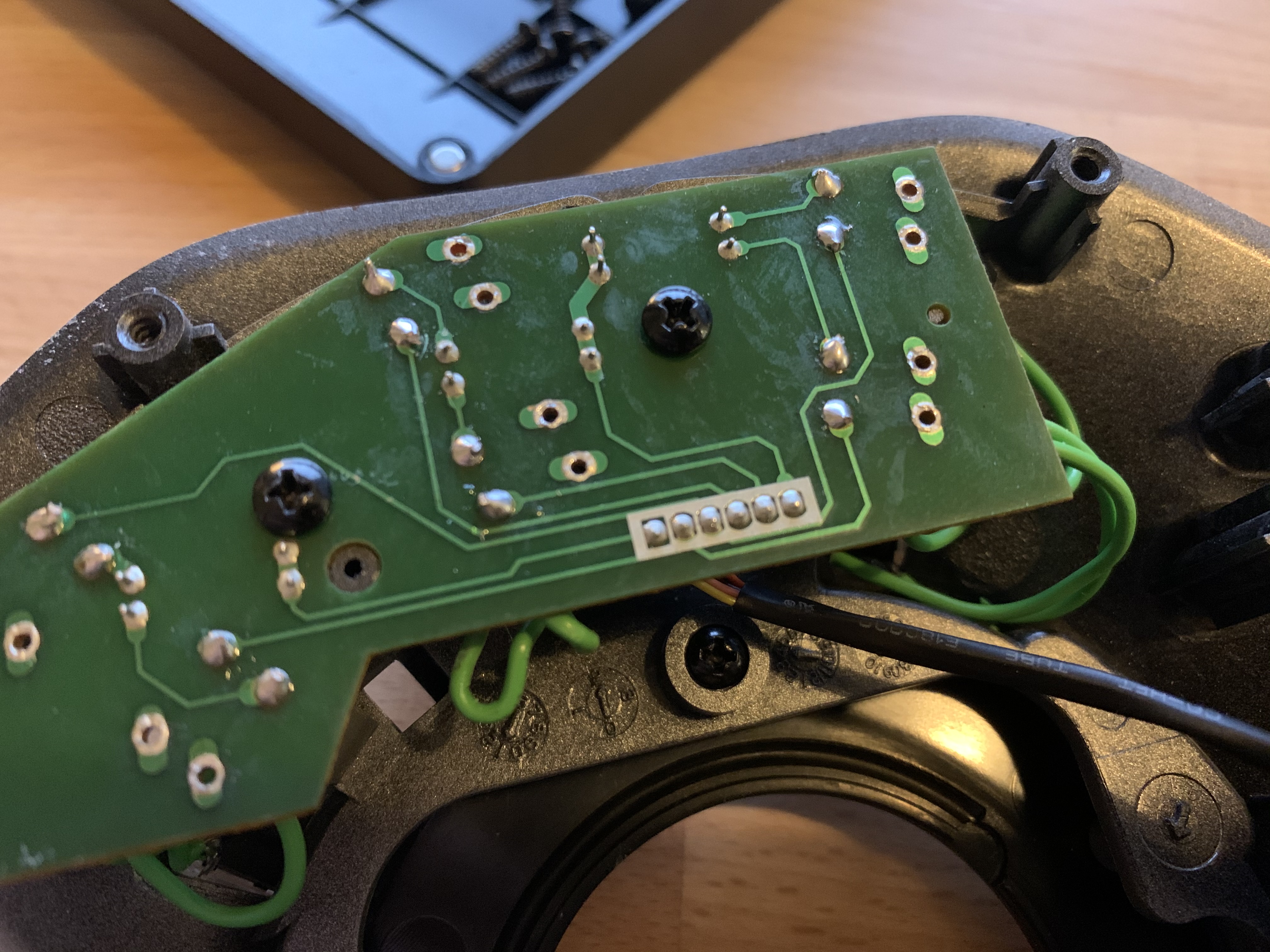
Well, happy for me, I happen to have “a few” mechanical switches around, meant for a mechanical keyboard. I usually have a small stock of Gateron Silent Browns or similar cheap tactile switches. But since this was a “game controller”, I decided to go with Kailh Choc V2 Browns that I had extra from an earlier project. I also had RAMA WORKS Grids from earlier keyboard projects. I checked out the iFixit article and soon realised that the base circuit board is just one-sided PCB. This should make my life really easy to do modifications!
I did the modifications on my Twitch channel, so I didn’t take any photos during the stream 😢
Here is a photo of the PCB, with the orignal switches desoldered. I used 24 AWG wire and soldered it to the places where the switches should be soldered and then the wires to the mechanical switches. The original button housings have enough space for Cherry MX type of switches. I just hotglued the switches on place.
Okay this worked fine and I was able to advance in my game of Star Wars: Squadrons and it worked marvelously. The buttons no longer were error prone and everything was great. The project was finished. Unless…
LogiMech
The PoC worked amazing, but as you can clearly see, the layout of the new buttons left something to hope for. Always go further and beyond, even in these crazy scientist kind of projects. That is how you learn and you are also able to make mistakes. Luckily, I didn’t do any mistakes, since I told about this project to my friend, ErkHal, who happens to run a business called PohjolaWorks. He got reaaally excited about this and sooner than I knew, I had to go and get a multimeter and start “reversing” the original PCB.
!](/images/logimech/pcb1.jpeg)
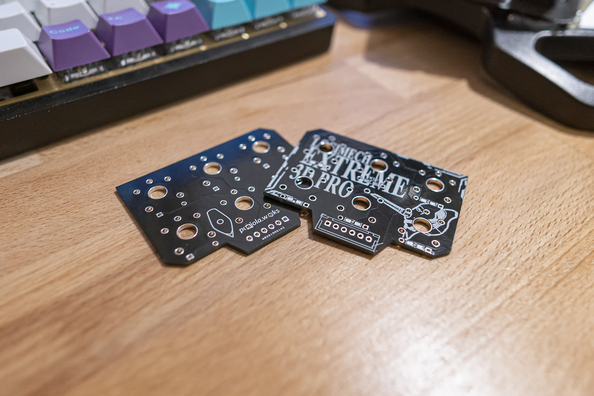
With the reversed schematics, I could start making a new PCB in KiCad. This was my first time ever downloading KiCad and therefore I didn’t get very far. I also had veeeery little time in my hands so I had to get ErkHal do all the hard work. Sooner than later, ErkHal sent me an amazing photo of the designed PCB.
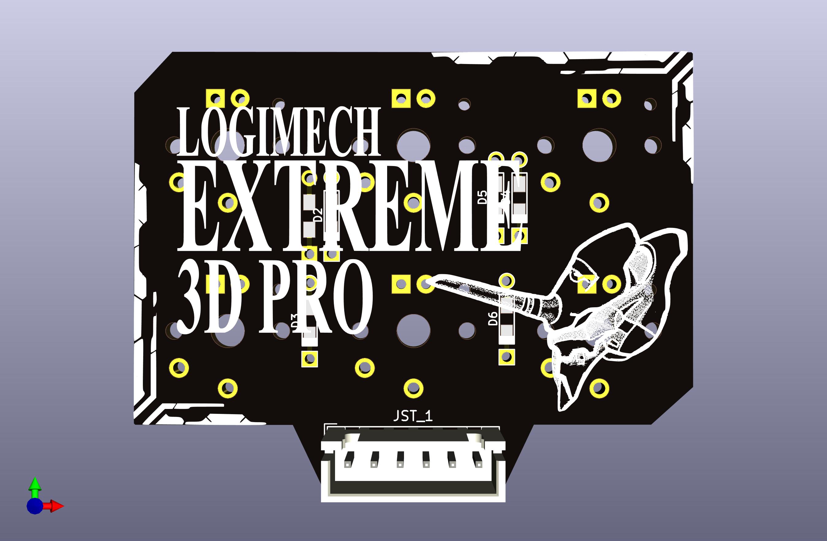
I am happy to say, that I helped out with the silkscreen and really not much with anything else. Whoops. EVA-01 best “mecha” btw. I got the gerber files from ErkHal and ordered the PCBs from PCBway. First time ever ordering a PCB! What an amazing feeling. Gerbers hold all the information of a PCB which the factory needs. If you need an assembled (components installed), you need to provide BOM and X-Y (for pick-and-place machines) files. This time I only needed to solder the connector, mechanical switches and couple of diodes. ErkHal was kind enough to add a footprint, which supports through-hole and SMD-soldered diodes. The diodes used are 1N4148 diodes, which are common in keyboard projects. This whole project has basically been a small keyboard.
You can get the gerber files from github.com/pohjolaworks/Logimech
Fast forward a few weeks and the PCBs arrived!
Assembly time!
The whole assembly process was, yet again, streamed on my Twitch channel, so no extra photos :(
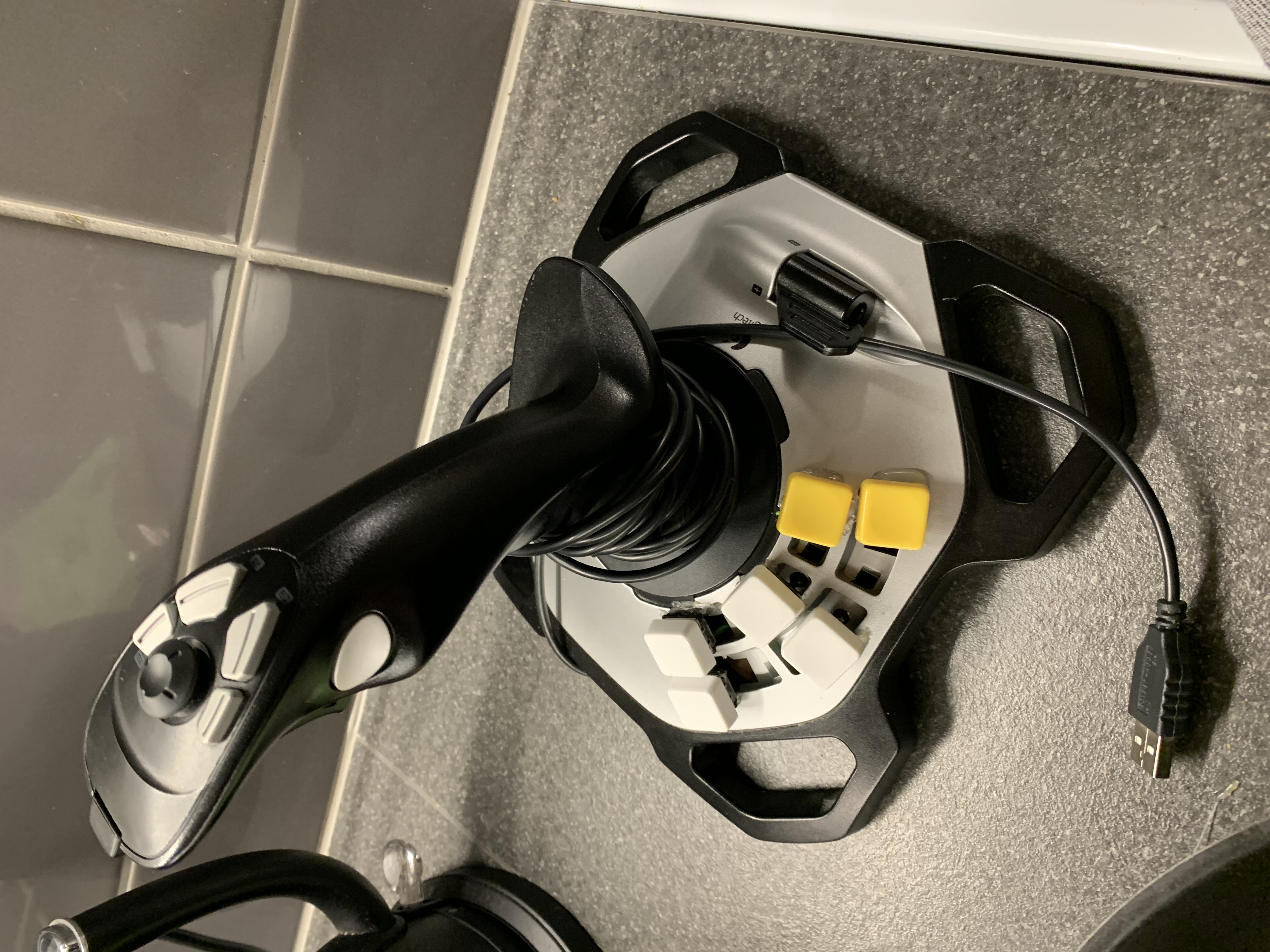
Okay so, you are able to “just” solder the switches to the PCB and mount the PCB, but you can also get a plate, where you mount the switches first. Yet again, I had leftover acrylic plate from PRKL30 project. I just snapped the plate for 6 switch places and was quite happy with it. The idea was to mount the plate somewhere on the joystick.
I started by desoldering the original connector from the original PCB. It was at this point I realised that the connector, as a matter of fact, was not a JST-connector. Or it was, but I also heard that there might not be thing called “standard JST-connector”. Damn. Anyways, I just added wires to the new PCB and soldered the end of those wires to the connector.
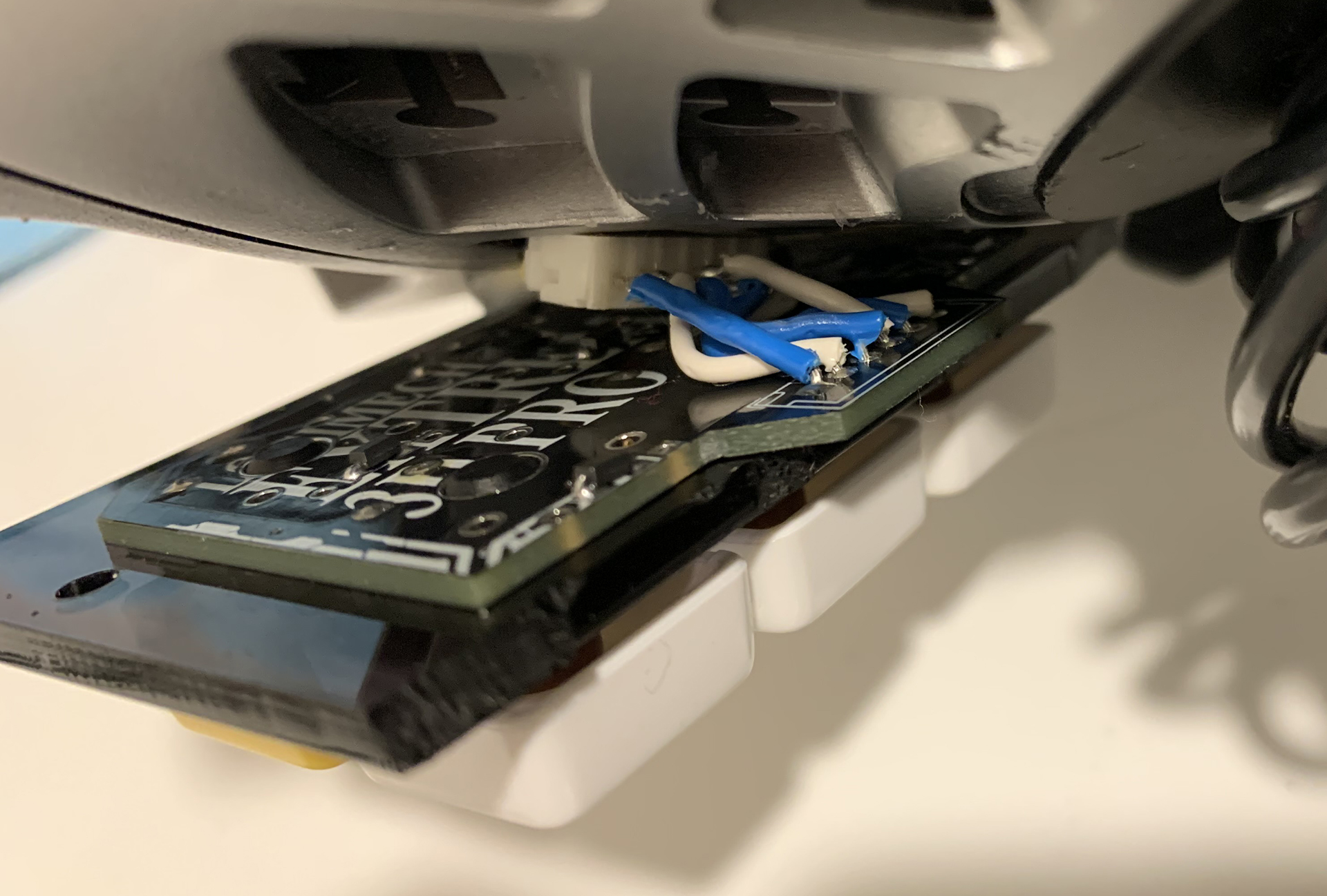
Anyways, after this, I needed to mount the plate somehow. The plate had a couple of screwholes, where I could be able to put standoffs and then screw the standoffs to the plate and the base of the joystick. I just lacked the resources for this neat and clean mounting style, so I went ham. With hotglue.
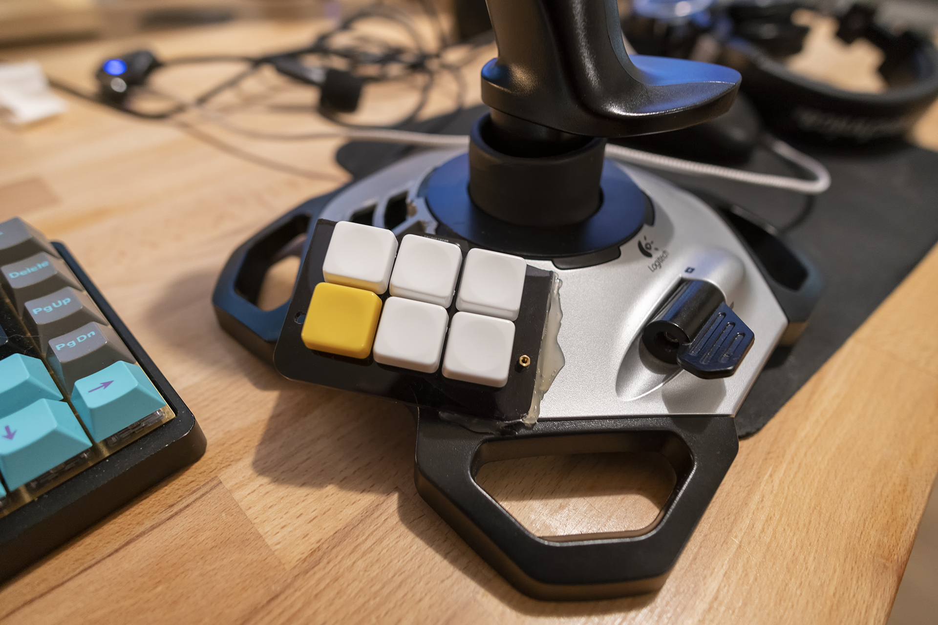
Now I can happily say that the project has been finished. The total cost was the prices for 6 switches and 5€ for 5 pieces of PCB from PCBway. So it was relatively cheap.
Lessons learned
Like in all projects, it is important to remember the stuff you learned from along the way. Mistakes are only okay if you learn from them!
- There is no such thing as a standard JST-connector
- You should get a multimeter. Maybe two. Just in case. Beepbeep.
- Kailh Choc V2 switches are bad. Get either V1s or just stick with normal MX-style switches
- Friends, who help and get excited for your projects, are amazing 🥰
- Take more photos during the project!
This was a really simple project, just swapping switches and making loads of simple solders. But nevertheless, it was a nice and funny project to do!
I dunno, the project might even get some updates in the future? 👀